Cat P5000 Throttle Control Switch Troubleshooting: A Comprehensive Guide
This guide details troubleshooting the Cat P5000’s throttle control switch, referencing available documentation for error codes and procedures.
It aids in diagnosing issues, utilizing service tools, and interpreting fault codes for effective repairs.
Understanding the Cat P5000 Throttle Control System
The Cat P5000 throttle control system is a critical component responsible for regulating engine power output, directly impacting machine performance and operator control. It relies on a sophisticated network of sensors, actuators, and the throttle control switch itself to translate operator input into precise engine adjustments. This system ensures smooth operation, optimal fuel efficiency, and adherence to emission standards.
The throttle control switch acts as the primary interface between the operator and the engine’s electronic control module (ECM). It transmits signals indicating the desired engine speed, which the ECM then interprets and adjusts accordingly. Understanding the system’s architecture – including the switch’s role within the broader control loop – is fundamental for effective troubleshooting. Documentation, like the referenced PDF, outlines the start sequence and provides insights into monitoring inputs and outputs, crucial for pinpointing faults within this complex system.
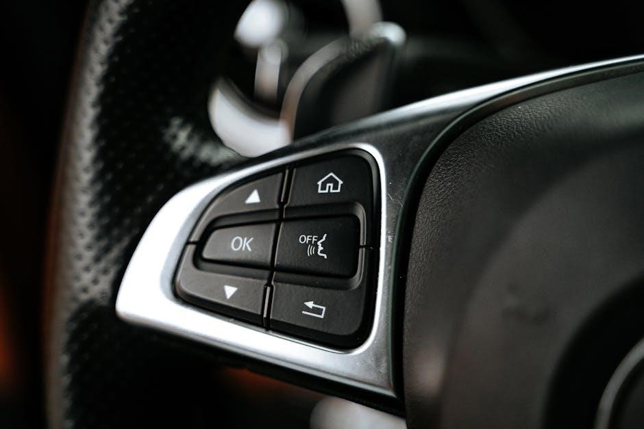
Identifying the Throttle Control Switch
Locating the throttle control switch on the Cat P5000 is the first step in any troubleshooting process. While the exact placement can vary slightly depending on the specific machine model, it’s generally found within the operator’s control panel, often integrated with the hand throttle lever or foot pedal assembly. Referencing the machine’s service manual or the troubleshooting PDF is crucial for precise identification.
The switch itself is typically a robust, sealed unit designed to withstand harsh operating environments. It often features multiple terminals for power, signal, and ground connections. Visual inspection should confirm its physical integrity – checking for damage to the housing, connector, or wiring harness. The PDF documentation may include detailed diagrams illustrating the switch’s location, wiring schematics, and connector pinouts, aiding in accurate identification and subsequent testing procedures.
Common Symptoms of a Faulty Throttle Control Switch
A malfunctioning throttle control switch on a Cat P5000 can manifest in several ways, impacting machine operation. Common symptoms include erratic engine speed, difficulty maintaining a consistent RPM, or a complete inability to control engine power. The engine may surge unexpectedly, stall frequently, or exhibit a delayed response to throttle adjustments. These issues can significantly reduce productivity and potentially create unsafe operating conditions.
The troubleshooting PDF documentation often correlates specific error codes with throttle switch failures. Operators may notice warning lights illuminating on the control panel, accompanied by diagnostic messages. Intermittent operation, where the throttle functions correctly at times and fails at others, is another telltale sign. A thorough review of the PDF’s symptom checklist, alongside a physical inspection, is vital for accurate diagnosis and repair.
Accessing the Troubleshooting PDF Documentation
The Cat P5000 throttle control switch troubleshooting PDF is typically available through several avenues. Caterpillar’s official website, specifically the “Service Information” or “Technical Documentation” sections, is a primary source. You’ll likely need the machine’s serial number for accurate document retrieval. Caterpillar dealers can also provide the PDF, either digitally or in printed format, often as part of a comprehensive service package.

Online forums dedicated to heavy equipment repair and maintenance may host copies of the PDF, though verifying the document’s authenticity and revision date is crucial. Some third-party service manual providers also offer downloadable PDFs for a fee. Ensure any downloaded document originates from a reputable source to avoid outdated or inaccurate information. The document provides vital insights into start sequences, error code explanations, and troubleshooting procedures for effective repairs.
Safety Precautions Before Troubleshooting
Prior to any troubleshooting of the Cat P5000 throttle control switch, strict adherence to safety protocols is paramount. Always disconnect the machine’s battery to prevent accidental activation of the engine or hydraulic systems during testing. Wear appropriate personal protective equipment (PPE), including safety glasses, gloves, and steel-toe boots.
Ensure the machine is parked on a level surface with the parking brake engaged. If lifting or working underneath the machine, utilize appropriate lifting devices and support stands. Be mindful of hot surfaces, moving parts, and potential electrical hazards. Consult the Cat P5000 operator’s manual for specific safety warnings and procedures related to the throttle control system. Never bypass safety devices or attempt repairs without proper training and understanding of the system’s operation.
Tools Required for Troubleshooting
Effective troubleshooting of the Cat P5000 throttle control switch necessitates a specific set of tools. A digital multimeter (DMM) is essential for testing switch continuity and voltage levels at the connector. Diagnostic software and a communication cable compatible with the Cat P5000’s electronic control module (ECM) are crucial for retrieving error codes and monitoring system parameters.
Standard hand tools, including screwdrivers, wrenches, and pliers, will be needed for accessing and removing the switch. A wiring diagram for the throttle control system is invaluable for identifying wires and connectors. A service manual specific to the Cat P5000 model provides detailed procedures and specifications. Additionally, a scan tool capable of reading manufacturer-specific codes can expedite the diagnostic process, alongside a reliable light source for visual inspections.
Step-by-Step Troubleshooting Procedure
Begin with a thorough visual inspection of the throttle control switch and its wiring harness, looking for any obvious damage like frayed wires, loose connections, or corrosion. Next, utilize a multimeter to test the switch’s continuity, verifying it opens and closes correctly according to its specifications; Subsequently, check for proper voltage at the switch connector while the engine is running, comparing readings to the service manual’s values.
If voltage is absent or incorrect, trace the wiring back to the ECM, checking for breaks or shorts. Employ diagnostic software to retrieve any stored error codes related to the throttle control system. Based on the codes, consult the documentation for specific troubleshooting steps. Document all findings and tests performed, ensuring a systematic approach to pinpoint the root cause of the issue.
Visual Inspection of the Switch and Wiring
Initiate the troubleshooting process with a detailed visual examination of the Cat P5000’s throttle control switch. Carefully inspect the switch housing for any physical damage, such as cracks or breaks, which could compromise its functionality. Pay close attention to the electrical connector, ensuring it’s securely fastened and free from corrosion. Examine the wiring harness leading to the switch, meticulously searching for signs of wear, fraying, or damage to the insulation.
Look for any evidence of rodent activity, as damaged wires can cause intermittent or complete failures. Check for loose or disconnected wires at both the switch and the ECM connections. A magnifying glass can be helpful for identifying subtle damage. Document any visual anomalies observed, as these findings will guide subsequent testing procedures and potentially reveal the source of the problem.
Testing Switch Continuity with a Multimeter
To assess the throttle control switch’s functionality, utilize a multimeter to perform a continuity test. Disconnect the switch from the electrical system to isolate it during testing. Set the multimeter to the continuity setting – typically indicated by a diode symbol or audible beep. Refer to the Cat P5000 wiring diagram to identify the correct terminals for testing.
Probe each terminal combination, observing the multimeter’s response. Continuity should be present when the switch is in its activated positions, and absent when it’s not. Compare your readings against the manufacturer’s specifications outlined in the service documentation. Intermittent or absent continuity indicates a faulty switch. Record all readings for comparison and documentation purposes. This test confirms whether the switch is internally broken or if the issue lies elsewhere in the circuit.
Checking for Voltage at the Switch Connector
Verify proper voltage supply to the throttle control switch connector using a multimeter. With the ignition switched on and the engine running (or key in the ‘on’ position, as specified in the service manual), carefully probe the connector terminals. Refer to the Cat P5000 wiring diagram to identify the power and ground pins.
Set the multimeter to DC voltage mode and measure the voltage between the power and ground terminals. The expected voltage should align with the system’s specifications – typically 5V or 12V. Absence of voltage indicates a problem upstream, such as a blown fuse, damaged wiring, or a faulty ECM. Document your findings. If voltage is present, proceed to testing the switch itself. Ensure proper grounding during the test to obtain accurate readings and avoid damaging the multimeter or the machine’s electrical system.

Interpreting Error Codes Related to the Throttle Control Switch
Error codes provide crucial diagnostic information regarding the throttle control switch. The Cat P5000’s Electronic Control Module (ECM) stores these codes when it detects anomalies. Accessing these codes requires a diagnostic tool compatible with Caterpillar engines. Documentation lists codes ranging from E03 to E40 and F01 to F89, though specific codes related to the throttle switch will vary.
Understanding the code’s definition is paramount. A code might indicate an open circuit, short to ground, or implausible signal from the switch. Refer to the official Cat troubleshooting PDF for a comprehensive list and detailed explanations. Don’t simply replace the switch based on a code; further testing, as outlined in this guide, is essential to pinpoint the root cause. Incorrect interpretation can lead to unnecessary repairs and downtime. Always clear the code after addressing the issue and verify it doesn’t reappear.
Common Error Codes and Their Meanings (Based on Available Documentation)
While specific codes vary by engine model and software version, several frequently appear related to the throttle control switch. Error code E03 often signals an issue with the engine speed sensor, potentially linked to the throttle position. Codes in the F01-F89 range can indicate communication faults within the control system, impacting throttle response.
A common finding is a code suggesting an implausible signal from the throttle position sensor. This doesn’t always mean the switch is faulty; wiring harness damage or a connector issue could be the culprit. Documentation highlights the importance of checking for voltage drops and continuity. Furthermore, certain codes may point to ECM internal failures, requiring professional diagnostics. Always consult the official Cat P5000 troubleshooting PDF for the most accurate and up-to-date code definitions and recommended actions before proceeding with repairs.
Replacing the Throttle Control Switch
If troubleshooting confirms a faulty throttle control switch, replacement is necessary. The Cat P5000 troubleshooting PDF details specific removal procedures, often involving disconnecting the wiring harness and unbolting the switch from its mounting bracket. Careful attention should be paid to the connector orientation during disconnection to avoid damage.
Installation involves reversing the removal process, ensuring the new switch is securely mounted and the connector is fully seated. The documentation stresses the importance of using the correct torque specifications for mounting bolts. Post-installation, a thorough inspection of the wiring harness for any damage is crucial. Always verify proper operation with diagnostic tools, as outlined in the PDF, before returning the equipment to service. Refer to the parts catalog for the correct switch part number.
Switch Removal Procedure
The Cat P5000 troubleshooting PDF outlines a precise switch removal process. Begin by disconnecting the negative battery cable to prevent electrical shock. Locate the throttle control switch and carefully disconnect the electrical connector, noting its orientation for reinstallation. The PDF emphasizes gentle handling to avoid damaging the connector terminals.
Next, remove any retaining hardware – typically bolts or screws – securing the switch to its mounting bracket. The document may specify torque values for these fasteners. Once the hardware is removed, carefully extract the switch, observing any associated wiring or brackets. Document the wiring configuration with a photograph before complete removal. Inspect the removed switch and surrounding area for any signs of physical damage or corrosion, as this may indicate related issues.
Switch Installation Procedure
The Cat P5000 troubleshooting PDF details a systematic switch installation. Begin by ensuring the mounting surface is clean and free of debris. Carefully position the new throttle control switch, aligning it with the mounting holes and any associated brackets. Secure the switch using the previously removed hardware, tightening to the torque specifications outlined in the PDF – crucial for proper operation and preventing damage.

Reconnect the electrical connector, ensuring correct orientation based on your pre-removal documentation or photographs. Gently seat the connector to avoid bent pins. Double-check all connections for security. Before reconnecting the battery, visually inspect the installation to confirm everything is properly positioned and secured. The PDF may recommend a final functional check before full system restoration, verifying the switch operates as expected.
Post-Replacement Testing and Verification
Following throttle control switch replacement on the Cat P5000, the troubleshooting PDF emphasizes thorough testing. Reconnect the battery and cycle the ignition, observing for any immediate error codes. Utilize the Cat diagnostic software (as detailed in the PDF) to clear any previously stored codes related to the switch.
Perform a functional test, carefully monitoring the engine’s response to throttle input across its entire range. Verify smooth and consistent operation without hesitation or erratic behavior. The PDF likely outlines specific parameters to monitor during this test. Confirm that the diagnostic software reports no new or recurring error codes. Document the test results, including any observed anomalies, for future reference. A successful test confirms proper installation and switch functionality, restoring optimal engine control.

Resources for Additional Information and Support
For comprehensive support beyond this guide and the Cat P5000 throttle control switch troubleshooting PDF, several resources are available. Caterpillar’s official website (https://www.cat.com/) provides access to detailed service manuals, parts diagrams, and technical bulletins. Local Cat dealerships offer expert assistance from trained technicians, capable of diagnosing complex issues and providing genuine replacement parts.

Online forums, such as mauforum.ru (though primarily Russian, translation tools can be helpful), may contain discussions and shared experiences from other Cat P5000 operators. Caterpillar’s service tools documentation, referenced in related PDFs, offers insights into diagnostic procedures. Remember to always prioritize official Caterpillar resources for accurate and reliable information when troubleshooting your equipment.